MiSUMi Wholesale Gas Spring Lift

Gas Spring Type:Free Mounting Direction Material Rod:S20C
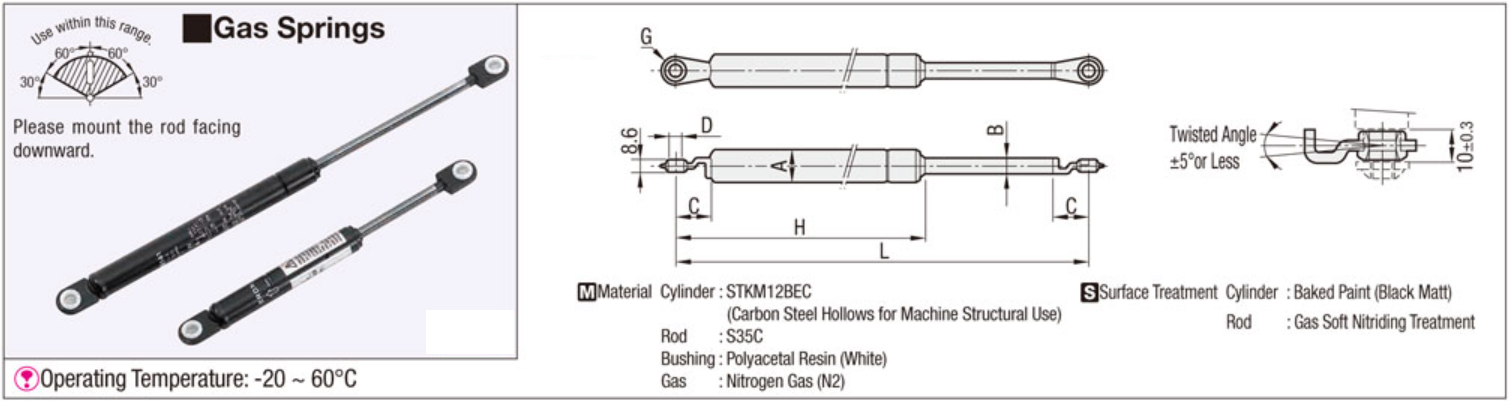
Material Cylinder:STKM11A (Carbon Steel Hollows for Machine Structural Use)
Operating Direction Range:360° Operating Temperature (°C):-20---60
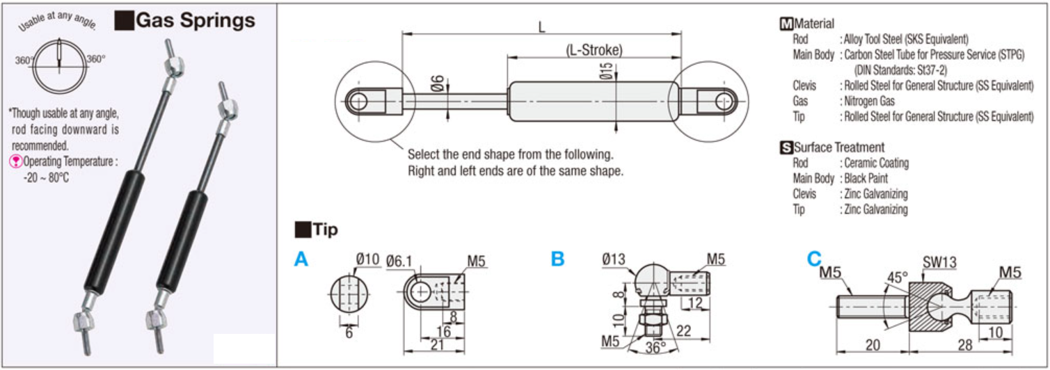
Type:Gas Springs
Gas Springs
• High pressure gas (Nitrogen gas: noncombustible) is sealed in a cylinder,and the gas reaction force is used as spring. Because this small gas spring receive small spring constant from large initial load in spite of its size, it can be
used for wide range of applications including machines, furniture, cars, office,automation equipments, etc.

Features
• In spite of its size and weight, large spring (reaction) force can be obtained.
• Spring (reaction) force is almost constant throughout its stroke.
• Can be designed as required for wide applications.
About Initial Selection
1. Calculate the necessary reaction force (F) through the following formula, then find out possible model types.
F : Necessary Reaction Force (at Max. Length)
F=WXA/B W : Weight of Doors, etc.
A : Horizontal Distance between Fulcrum (Door Hinge, etc.) and the Center of Gravity
B : Vertical Distance between Fulcrum (Door Hinge, etc.) and the Axis of Gas Spring
2. Select Fx1.1 or more for the gas spring reaction force.
Gas reaction forces may vary within about 10%.
3. If required reaction force (Fx1.1) is larger than the reaction
force at the max. length of gas spring -( ) mm, use 2 or
more springs.
4. Reaction forces are designed at 20°C. Reaction forces
increase or decrease as the temperature changes.
Precautions for Use (for FGS, GSS, FGSS, HFGSS and FRGSS)
• Pay attention to temperature of gas springs during use. Do not store for prolonged duration. It will cause premature seal deterioration and reaction force decline.
(Product Temperature Range: GSS, FGSS: -20°C ~ 60°C / HFGSS: -20°C ~ 80°C / FRGSS: -30°C ~ 80°C Some products have different temperature range.Confirm on each product page.)
• Gas reaction forces are slightly different among individual products and may change depending on the temperature.
• Reaction force may decrease depending on the operating condition and times of use. Please replace it when it cannot reach the necessary reaction force.
• Do not store or use in the environments where the rod may rust, or in chemical atmosphere. Furthermore, do not paint the gas spring.
• Do not damage the cylinders and rods. If rods are wrapped with tape or plastic strings, adhesives or fibers remained on the surface will come inside, resulting in gas/oil leakage. Be sure to see if there is no rust, scratches, adhesives and foreign objects on the rod before use.
• Do not apply forces like bending load and torsion. Receiving load only with gas springs results in unbalanced load, which causes early deterioration and gas/oil leakage. For rotating motion, be sure to secure smooth sliding on the hinge. For linear motion, install a guide, etc. to prevent unbalanced load.
• Do not extend gas springs beyond its max. length. Even in the max. stroke (during compression), it must remain about 10mm away from the stroke end. Do not extend and compress at high speeds (with 1m/s or more).
• Use FGS and GSS with the cylinder side up and the rod side down, so that internal oil protects the rubber seal. For FGS, GSS and FRGSS, do not tilt more than 60 degrees. When it is necessary to temporarily store, do not tilt more than 60 degrees.
• Although there is no restriction in the use angle for the FGSS and HFGSS, rod downward is recommended.
Features of Mounting Orientation Free Gas Springs (FGSS)
• Mounting Orientation Free Gas Springs
1. Nitrogen gas (non-combustible) is sealed in the gas chamber C with a free moving piston intervening, and gas reaction force is used as a spring.
2. Gas chamber C has a constant reaction force in extending direction since it pressurizes oil chamber AB. Therefore the size of reaction force depends on the inner pressure of gas chamber C.
3. When rod moves from the predetermined position, oil in chamber AB moves through orifice hole of the piston.
4. The rod volume change in the cylinder is adjusted by the change of gas chamber C.
Gas reaction force at the max. length -10 (5) mm and the max. length -(s) mm are listed in this catalog. Gas reaction force generally changes proportionately. If the gas reaction force on a certain stroke is required, connect the 2 points with a straight line as shown in Fig. 3 and read the value on the stroke to conjecture.


| Part Number | Max. Length Lmax | Min. Length Lmin | Stroke | Gas Reaction Force(20°C) | A | B | H | Applicable Mounting Bracket |
Weight(g) | |||||
| Lmax. -10mm Stroke | Lmax.-(S)mm Stroke | |||||||||||||
| Fa | Fb | (S) | ||||||||||||
| Type | NO. | N | kgf | N | kgf | |||||||||
| FGSS | 15050A | 246 | 196 | 50 | 49 | 5 | 69 | 7 | 40 | 15 | 7 | 164 | GSBR8A-S GSBR8B-S GSBR8C-S GSBR8D-S (P.384) | 125 |
| 15050K | 70 | 7.1 | 90 | 9.1 | ||||||||||
| 15050B | 98 | 10 | 127 | 13 | ||||||||||
| 15080A | 330 | 250 | 80 | 49 | 5 | 69 | 7 | 70 | 218 | 150 | ||||
| 15080B | 98 | 10 | 127 | 13 | ||||||||||
| 15090A | 360 | 270 | 90 | 49 | 5 | 69 | 7 | 80 | 238 | 155 | ||||
| 15090B | 98 | 10 | 127 | 13 | ||||||||||
| 15100A | 386 | 286 | 100 | 49 | 5 | 69 | 7 | 90 | 254 | 170 | ||||
| 15100B | 98 | 10 | 127 | 13 | ||||||||||
| 18100A | 386 | 286 | 100 | 196 | 20 | 255 | 26 | 18 | 8 | 253 | 210 | |||
| 18100B | 294 | 30 | 382 | 39 | ||||||||||
| 18150A | 526 | 376 | 150 | 196 | 20 | 265 | 27 | 140 | 343 | 280 | ||||
| 18150B | 294 | 30 | 392 | 40 | ||||||||||
| 22050A | 246 | 196 | 50 | 196 | 20 | 265 | 27 | 40 | 22 | 10 | 163 | 215 | ||
| 22050B | 294 | 30 | 402 | 41 | ||||||||||
| 22050C | 392 | 40 | 529 | 54 | ||||||||||
| 22050D | 490 | 50 | 655 | 66 | ||||||||||
| 22080A | 330 | 250 | 80 | 196 | 20 | 274 | 28 | 70 | 217 | 270 | ||||
| 22080B | 294 | 30 | 412 | 42 | ||||||||||
| 22080C | 392 | 40 | 539 | 55 | ||||||||||
| 22080D | 490 | 50 | 675 | 68 | ||||||||||
| 22090A | 360 | 270 | 90 | 196 | 20 | 265 | 27 | 80 | 237 | 280 | ||||
| 22090B | 294 | 30 | 402 | 41 | ||||||||||
| 22090C | 392 | 40 | 529 | 54 | ||||||||||
| 22090D | 490 | 50 | 659 | 67 | ||||||||||
| 22100A | 386 | 286 | 100 | 196 | 20 | 274 | 28 | 90 | 253 | 305 | ||||
| 22100B | 294 | 30 | 412 | 42 | ||||||||||
| 22100C | 392 | 40 | 549 | 56 | ||||||||||
| 22120A | 440 | 320 | 120 | 196 | 20 | 274 | 28 | 110 | 287 | 320 | ||||
| 22120B | 294 | 30 | 402 | 41 | ||||||||||
| 22120C | 392 | 40 | 539 | 55 | ||||||||||
| 22120D | 490 | 50 | 672 | 68 | ||||||||||
| 22130A | 470 | 340 | 130 | 196 | 20 | 274 | 28 | 120 | 307 | 330 | ||||
| 22130B | 294 | 30 | 402 | 41 | ||||||||||
| 22130C | 392 | 40 | 539 | 55 | ||||||||||
| 22150A | 526 | 376 | 150 | 196 | 20 | 274 | 28 | 140 | 343 | 400 | ||||
| 22150B | 294 | 30 | 402 | 41 | ||||||||||
| 22150C | 392 | 40 | 539 | 55 | ||||||||||
| 22180A | 610 | 430 | 180 | 196 | 20 | 274 | 28 | 170 | 397 | 420 | ||||
| 22180B | 294 | 30 | 402 | 41 | ||||||||||
| 22180C | 392 | 40 | 539 | 55 | ||||||||||
| 22200A | 666 | 466 | 200 | 196 | 20 | 265 | 27 | 190 | 433 | 480 | ||||
| 22200B | 294 | 30 | 402 | 41 | ||||||||||
| 22200C | 392 | 40 | 529 | 54 | ||||||||||
| 22250A | 750 | 500 | 250 | 196 | 20 | 304 | 31 | 240 | 467 | 540 | ||||
| 22250B | 294 | 30 | 451 | 46 | ||||||||||
| 22250C | 392 | 40 | 598 | 61 | ||||||||||
| 22300A | 850 | 550 | 300 | 196 | 20 | 323 | 33 | 290 | 517 | 600 | ||||
| 22300B | 294 | 30 | 490 | 50 | ||||||||||
| 27150A | 526 | 376 | 150 | 490 | 50 | 657 | 67 | 140 | 27.4 | 12.5 | 351 | GSBR8F-S (P.384) | 610 | |
| 27150B | 588 | 60 | 784 | 80 | ||||||||||
| 27150C | 686 | 70 | 921 | 94 | ||||||||||
| 27200A | 666 | 466 | 200 | 490 | 50 | 657 | 67 | 190 | 441 | 760 | ||||
| 27200B | 588 | 60 | 784 | 80 | ||||||||||
| 27200C | 686 | 70 | 921 | 94 | ||||||||||
| 27250A | 750 | 500 | 250 | 490 | 50 | 725 | 74 | 240 | 475 | 900 | ||||
| 27250B | 588 | 60 | 872 | 89 | ||||||||||
| 27250C | 686 | 70 | 1019 | 104 | ||||||||||
| 27300A | 850 | 550 | 300 | 490 | 50 | 774 | 79 | 290 | 525 | 1000 | ||||
| 27300B | 588 | 60 | 931 | 95 | ||||||||||

Gas spring that is a limited type in mounting direction. You can choose the stroke from 49 to 360 mm.
Gas Spring Type:Mounting Orientation Limited Type
Material Rod:S20C
Material Cylinder:STKM11A (Carbon Steel Hollows for Machine Structural Use)
Operating Direction Range:Within 60゚ with Rod Facing Downward
Type:Gas Springs
Catalog

| Part Number | Max. Length Lmax | Min. Length Lmin | Stroke | Gas Reaction Force(20°C) | O.D | Rod Dia | H | Applicable Mounting Bracket |
Weight(g) | |||||
| Lmax. -10mm Stroke | Lmax.-(S)mm Stroke | |||||||||||||
| Fa | Fb | (S) | ||||||||||||
| Type | NO.- Reaction Force (Fa) |
N | kgf | N | kgf | A | B | |||||||
| FGSS | 15049-030 | 181 | 132 | 49 | 30 | 3.0 | 40 | 4.1 | 39 | 15 | 7 | 110 | GSBR6A GSBR6B GSBR6C GSBR6D (P384) |
83 |
| 15049-055 | 55 | 6.0 | 71 | 7.2 | ||||||||||
| 15049-070 | 70 | 7.1 | 89 | 9.0 | ||||||||||
| 15049-085 | 85 | 9.0 | 109 | 11.1 | ||||||||||
| 15049-150 | 150 | 15.0 | 191 | 19.5 | ||||||||||
| 15069-050 | 221 | 152 | 69 | 50 | 5.0 | 67 | 6.8 | 59 | 130 | 96 | ||||
| 15069-080 | 80 | 8.0 | 107 | 10.9 | ||||||||||
| 15069-100 | 100 | 10.2 | 132 | 13.4 | ||||||||||
| 15069-120 | 120 | 12.0 | 158 | 16.1 | ||||||||||
| 15089-070 | 261 | 172 | 89 | 70 | 7.0 | 94 | 9.6 | 79 | 150 | 109 | ||||
| 15089-085 | 85 | 8.7 | 115 | 11.7 | ||||||||||
| 15089-100 | 100 | 10.0 | 135 | 13.8 | ||||||||||
| 15089-150 | 150 | 15.0 | 202 | 20.6 | ||||||||||
| 15089-200 | 200 | 20.0 | 268 | 27.3 | ||||||||||
| 15099-075 | 281 | 182 | 99 | 75 | 8.0 | 101 | 10.3 | 89 | 160 | 116 | ||||
| 15099-120 | 120 | 12.0 | 162 | 16.5 | ||||||||||
| 15099-200 | 200 | 20.0 | 270 | 27.6 | ||||||||||
| 18099-300 | 281 | 184 | 97 | 300 | 30.5 | 392 | 39.9 | 18 | 8 | |||||
| 18099-400 | 400 | 40.7 | 522 | 53.2 | ||||||||||
| 18120-100 | 365 | 245 | 120 | 100 | 10.0 | 123 | 13.0 | 110 | 221 | 183 | ||||
| 18120-200 | 200 | 20.0 | 245 | 25.0 | ||||||||||
| 18120-300 | 300 | 31.0 | 367 | 37.0 | ||||||||||
| 18120-400 | 400 | 41.0 | 489 | 50.0 | ||||||||||
| 18150-100 | 420 | 270 | 150 | 100 | 10.0 | 126 | 12.9 | 140 | 246 | 205 | ||||
| 18150-150 | 150 | 15.0 | 188 | 19.2 | ||||||||||
| 18120-200 | 200 | 20.0 | 251 | 25.6 | ||||||||||
| 18150-250 | 250 | 26.0 | 313 | 31.9 | ||||||||||
| 18200-100 | 525 | 325 | 200 | 100 | 10.0 | 127 | 13.0 | 190 | 301 | 248 | ||||
| 18200-150 | 150 | 15.0 | 190 | 19.4 | ||||||||||
| 18200-200 | 200 | 20.0 | 253 | 25.8 | ||||||||||
| 18200-300 | 300 | 31.0 | 379 | 38.7 | ||||||||||
| 22250-100 | 635 | 385 | 250 | 100 | 10.0 | 129 | 13.2 | 240 | 22 | 10 | 352 | GSBR8A GSBR8B GSBR8C GSBR8D (P384) |
409 | |
| 22250-150 | 150 | 15.2 | 193 | 19.6 | ||||||||||
| 22250-200 | 200 | 20.0 | 257 | 26.2 | ||||||||||
| 22250-300 | 300 | 31.0 | 384 | 39.2 | ||||||||||
| 22250-400 | 400 | 41.0 | 511 | 52.1 | ||||||||||
| 22270-345 | 670 | 400 | 270 | 345 | 35.0 | 528 | 53.9 | 260 | 12.5 | 367 | 531 | |||
| 22270-500 | 500 | 51.0 | 763 | 77.9 | ||||||||||
| 22270-700 | 700 | 71.0 | 1065 | 108.7 | ||||||||||
| 22290-745 | 700 | 410 | 290 | 745 | 76.0 | 1160 | 118.4 | 280 | 377 | 556 | ||||
| 22290-845 | 845 | 86.0 | 1314 | 134.1 | ||||||||||
| 22300-200 | 740 | 440 | 300 | 200 | 20.0 | 257 | 26.2 | 290 | 10 | 407 | 469 | |||
| 22300-250 | 250 | 26.0 | 321 | 32.8 | ||||||||||
| 22300-300 | 300 | 31.0 | 385 | 39.3 | ||||||||||
| 22360-215 | 833 | 473 | 360 | 215 | 22.0 | 284 | 29.0 | 350 | 440 | 523 | ||||
| 22360-345 | 345 | 35.0 | 456 | 46.5 | ||||||||||
| Part Number | Max. Length Lmax | Min. Length Lmin | Stroke | Gas Reaction Force(20°C) | A | B | C1 | C2 | D | G | H | Applicable Mounting Bracket |
Weight(g) | |||||
| Lmax. -10mm Stroke | Lmax.-(S)mm Stroke | |||||||||||||||||
| Fa | Fb | (S) | ||||||||||||||||
| Type | NO.- Reaction Force (Fa) |
N | kgf | N | kgf | |||||||||||||
| FGSS | 15050A | 181 | 131 | 50 | 27 | 2.8 | 32 | 3.4 | 40 | 15 | 6 | 15 | 15 | 7 | R8 | 110 | GSSB6A | 75 |
| 15050B | 85 | 8.7 | 102 | 10.4 | ||||||||||||||
| 15050C | 147 | 15.0 | 175 | 17.9 | ||||||||||||||
| 15050D | 186 | 19.0 | 222 | 22.7 | ||||||||||||||
| 15050E | 206 | 21.0 | 245 | 25.0 | ||||||||||||||
| 15070A | 221 | 151 | 70 | 81 | 8.3 | 102 | 10.4 | 60 | 131 | 90 | ||||||||
| 15070B | 119 | 12.1 | 124 | 12.7 | 42 | |||||||||||||
| 15070C | 196 | 20.0 | 245 | 25.0 | 60 | |||||||||||||
| 15090A | 261 | 171 | 90 | 69 | 7.0 | 89 | 9.1 | 80 | 150 | 108 | ||||||||
| 15090B | 79 | 8.1 | 103 | 10.5 | ||||||||||||||
| 15090C | 88 | 9.0 | 115 | 11.7 | ||||||||||||||
| 15090D | 147 | 15.0 | 191 | 19.5 | ||||||||||||||
| 15090E | 196 | 20.0 | 254 | 25.9 | 151 | |||||||||||||
| 15100A | 281 | 181 | 100 | 76 | 7.8 | 103 | 10.5 | 90 | 161 | 120 | ||||||||
| 15100K | 110 | 11.2 | 147 | 15.0 | 161 | |||||||||||||
| 15100B | 196 | 20.0 | 257 | 26.2 | 120 | |||||||||||||
| 18090A | 261 | 171 | 90 | 263 | 26.8 | 343 | 35.0 | 80 | 18 | 8 | 151 | 170 | ||||||
| 18100A | 281 | 181 | 100 | 324 | 33.1 | 428 | 43.7 | 90 | 161 | 190 | ||||||||
| 22080K | 279 | 199 | 80 | 116 | 11.8 | 142 | 14.5 | 70 | 22 | 10 | 24 | 24 | 9 | R10 | 171 | GSSB8A GSSB8B GSSB8C GSSB8D GSSB8E |
178 | |
| 22080A | 196 | 20.0 | 237 | 24.2 | 169.5 | |||||||||||||
| 22080B | 246 | 25.1 | 299 | 30.5 | ||||||||||||||
| 22096A | 306 | 210 | 96 | 392 | 40.0 | 494 | 50.4 | 86 | 186 | 195 | ||||||||
| 22142A | 472 | 330 | 142 | 279 | 28.5 | 372 | 38.0 | 125 | 306 | 300 | ||||||||
| 22147A | 412 | 265 | 147 | 147 | 15.0 | 194 | 19.8 | 130 | 241 | 265 | ||||||||
| 22147B | 240 | 24.5 | 314 | 32.0 | ||||||||||||||
| 22150A | 464 | 314 | 150 | 343 | 35.0 | 408 | 41.6 | 140 | 286 | 310 | ||||||||
| 22210A | 567 | 365.5 | 210.5 | 587 | 59.9 | 799 | 81.5 | 179 | 13 | 20 | R15 | 330.5 | 460 | |||||
| 22210B | 667 | 68.1 | 908 | 92.7 | ||||||||||||||
| 22235A | 580 | 334.5 | 235.5 | 129 | 13.2 | 195 | 19.9 | 206 | 10 | 24 | R10 | 320.5 | 370 | |||||
| 22235B | 248 | 25.3 | 314 | 32.0 | 208 | |||||||||||||
| 22235C | 343 | 35.0 | 435 | 44.4 | 206 | |||||||||||||
| 22235D | 507 | 51.7 | 642 | 65.5 | ||||||||||||||
| 22243A | 627 | 384 | 243 | 196 | 20.0 | 301 | 30.7 | 215 | 12.5 | 376 | 470 | |||||||
| 22243B | 433 | 44.2 | 657 | 67.0 | 360 | |||||||||||||
| 22253A | 675 | 421.5 | 253.5 | 311 | 31.7 | 367 | 37.4 | 197 | 10 | 397.5 | 430 | |||||||
| 22270K | 670 | 400 | 270 | 127 | 13.0 | 190 | 19.4 | 240 | 12.5 | 376 | 500 | |||||||
| 22270A | 343 | 35.0 | 497 | 50.7 | ||||||||||||||
| 22270L | 406 | 41.4 | 588 | 60.0 | 10 | 372 | 460 | |||||||||||
| 22270B | 507 | 51.7 | 739 | 75.4 | 12.5 | 376 | 500 | |||||||||||
| 22270C | 596 | 60.8 | 868 | 88.6 | ||||||||||||||
| 22270D | 755 | 77.0 | 1104 | 112.7 | ||||||||||||||
| 22300K | 700 | 400 | 300 | 596 | 60.8 | 966 | 98.6 | 290 | 20 | 20 | 380 | 535 | ||||||
| 22300A | 745 | 76.0 | 1160 | 118.4 | 275 | 376 | 525 | |||||||||||
| 22300B | 850 | 86.7 | 1320 | 134.7 | ||||||||||||||
| 22315A | 795 | 480 | 315 | 833 | 85.0 | 1220 | 124.5 | 305 | 24 | 24 | 452 | 620 | ||||||
| 22356A | 833 | 477 | 356.5 | 216 | 22.0 | 288 | 29.4 | 350 | 10 | 530 | ||||||||
| 22356B | 345 | 35.2 | 460 | 46.9 | ||||||||||||||
| Part Number | Gas Reaction Force(20°C}N Max. Length -5mm | Lmax | Gas Reaction Force(20°C}N Max. Length +5mm | Weight (g) | ||
| Type | Tip Shape | Stroke | ||||
| HFGSS | A B C | 40 | N 20~400 10N Increment | 106 | 126% | 49 |
| 50 | 126 | 55 | ||||
| 60 | 146 | 61 | ||||
| 80 | 186 | 73 | ||||
| 100 | 226 | 84 | ||||
| 120 | 266 | 96 | ||||
| 150 | 326 | 128% | 113 | |||
| Part Number | Gas Reaction Force(20°C)N Max. Length -5mm | Lmax | M | A | B | Weight (g) | ||
| Type | Tip Shape | Stroke | ||||||
| FRGSS | A B | 60 | 100 (10.2kgf) | 171 | 104.5 | 18 | 8 | 140 |
| 125(12.8kgf) | ||||||||
| 150(15.3kgf) | ||||||||
| 200(20.4kgf) | ||||||||
| 80 | 100(10.2kgf) | 211 | 126.5 | 190 | ||||
| 150 (15.3kgf) | ||||||||
| 200(20.4kgf) | ||||||||
| 300 (30.6kgf) | ||||||||
| 100 | 100(10.2kgf) | 251 | 145.5 | 200 | ||||
| 200(20.4kgf) | ||||||||
| 300 (30.6kgf) | ||||||||
| 400(40.8kgf) | ||||||||
Part number
| Part Number | Min. Length Lmin (mm) | Gas Reaction Force 1 (at Max. Length - 10mm Stroke) (N) | Stroke (mm) | Rod Dia. (B) (Ø) | Cylinder Dia. (A) (Ø) | Max. Length Lmax (mm) | Operating Temperature (°C) | Minimum order quantity |
| FGS15049-030 | 132 | 30 | 49 | 7 | 15 | 181 | 0~60 | 1 Piece(s) |
| FGS15049-055 | 132 | 55 | 49 | 7 | 15 | 181 | 0~60 | 1 Piece(s) |
| FGS15049-070 | 132 | 70 | 49 | 7 | 15 | 181 | -20~60 | 1 Piece(s) |
| FGS15049-085 | 132 | 85 | 49 | 7 | 15 | 181 | 0~60 | 1 Piece(s) |
| FGS15049-150 | 132 | 150 | 49 | 7 | 15 | 181 | 0~60 | 1 Piece(s) |
| FGS15069-050 | 152 | 50 | 69 | 7 | 15 | 221 | -20~60 | 1 Piece(s) |
| FGS15069-080 | 152 | 80 | 69 | 7 | 15 | 221 | -20~60 | 1 Piece(s) |
| FGS15069-100 | 152 | 100 | 69 | 7 | 15 | 221 | -20~60 | 1 Piece(s) |
| FGS15069-120 | 152 | 120 | 69 | 7 | 15 | 221 | -20~60 | 1 Piece(s) |
| FGS15089-070 | 172 | 70 | 89 | 7 | 15 | 261 | -20~60 | 1 Piece(s) |
| FGS15089-085 | 172 | 85 | 89 | 7 | 15 | 261 | -20~60 | 1 Piece(s) |
| FGS15089-100 | 172 | 100 | 89 | 7 | 15 | 261 | -20~60 | 1 Piece(s) |
| FGS15089-150 | 172 | 150 | 89 | 7 | 15 | 261 | -20~60 | 1 Piece(s) |
| FGS15089-200 | 172 | 200 | 89 | 7 | 15 | 261 | -20~60 | 1 Piece(s) |
| FGS15099-075 | 182 | 75 | 99 | 7 | 15 | 281 | -20~60 | 1 Piece(s) |
| FGS15099-120 | 182 | 120 | 99 | 7 | 15 | 281 | -20~60 | 1 Piece(s) |
| FGS15099-200 | 182 | 200 | 99 | 7 | 15 | 281 | -20~60 | 1 Piece(s) |
| FGS18099-300 | 184 | 300 | 97 | 8 | 18 | 281 | -20~60 | 1 Piece(s) |
| FGS18099-400 | 184 | 400 | 97 | 8 | 18 | 281 | -20~60 | 1 Piece(s) |
| FGS18120-100 | 245 | 100 | 120 | 8 | 18 | 365 | -20~60 | 1 Piece(s) |
| FGS18120-200 | 245 | 200 | 120 | 8 | 18 | 365 | -20~60 | 1 Piece(s) |
| FGS18120-300 | 245 | 300 | 120 | 8 | 18 | 365 | -20~60 | 1 Piece(s) |
| FGS18120-400 | 245 | 400 | 120 | 8 | 18 | 365 | -20~60 | 1 Piece(s) |
| FGS18150-100 | 270 | 100 | 150 | 8 | 18 | 420 | -20~60 | 1 Piece(s) |
| FGS18150-150 | 270 | 150 | 150 | 8 | 18 | 420 | -20~60 | 1 Piece(s) |
| FGS18150-200 | 270 | 200 | 150 | 8 | 18 | 420 | -20~60 | 1 Piece(s) |
| FGS18150-250 | 270 | 250 | 150 | 8 | 18 | 420 | -20~60 | 1 Piece(s) |
| FGS18200-100 | 325 | 100 | 200 | 8 | 18 | 525 | -20~60 | 1 Piece(s) |
| FGS18200-150 | 325 | 150 | 200 | 8 | 18 | 525 | -20~60 | 1 Piece(s) |
| FGS18200-200 | 325 | 200 | 200 | 8 | 18 | 525 | -20~60 | 1 Piece(s) |
| FGS18200-300 | 325 | 300 | 200 | 8 | 18 | 525 | -20~60 | 1 Piece(s) |
| FGS22250-100 | 385 | 100 | 250 | 10 | 22 | 635 | -20~60 | 1 Piece(s) |
| FGS22250-150 | 385 | 150 | 250 | 10 | 22 | 635 | -20~60 | 1 Piece(s) |
| FGS22250-200 | 385 | 200 | 250 | 10 | 22 | 635 | -20~60 | 1 Piece(s) |
| FGS22250-300 | 385 | 300 | 250 | 10 | 22 | 635 | -20~60 | 1 Piece(s) |
| FGS22250-400 | 385 | 400 | 250 | 10 | 22 | 635 | -20~60 | 1 Piece(s) |
| FGS22270-345 | 400 | 345 | 270 | 12.5 | 22 | 670 | -20~60 | 1 Piece(s) |
| FGS22270-500 | 400 | 500 | 270 | 12.5 | 22 | 670 | -20~60 | 1 Piece(s) |
| FGS22270-700 | 400 | 700 | 270 | 12.5 | 22 | 670 | -20~60 | 1 Piece(s) |
| FGS22290-745 | 410 | 745 | 290 | 12.5 | 22 | 700 | -20~60 | 1 Piece(s) |
| FGS22290-845 | 410 | 845 | 290 | 12.5 | 22 | 700 | -20~60 | 1 Piece(s) |
| FGS22300-200 | 440 | 200 | 300 | 10 | 22 | 740 | -20~60 | 1 Piece(s) |
| FGS22300-250 | 440 | 250 | 300 | 10 | 22 | 740 | -20~60 | 1 Piece(s) |
| FGS22300-300 | 440 | 300 | 300 | 10 | 22 | 740 | -20~60 | 1 Piece(s) |
| FGS22360-215 | 473 | 215 | 360 | 10 | 22 | 833 | -20~60 | 1 Piece(s) |
| FGS22360-345 | 473 | 345 | 360 | 10 | 22 | 833 | -20~60 | 1 Piece(s) |
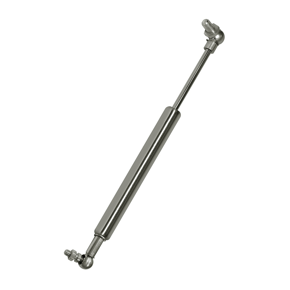
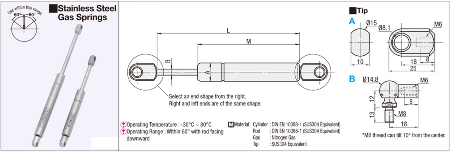
A stainless steel gas spring. [Type of Gas Spring]A gas reaction force specified type.
Gas Spring Type:Gas Reaction Force Configurable Type
Material Rod:DIN EN 10088-1(SUS304 Equivalent)
Material Cylinder:DIN EN 10088-1(SUS304 Equivalent)
Rod Dia. (B) (Ø) :8
Cylinder Dia. (A) (Ø):18
Operating Direction Range:Within 60゚ with Rod Facing Downward
Operating Temperature (°C):-30——80
Type:Gas Springs
| Part Number | Stroke(mm) | Cylinder End Shape | Rod End Shape | Max. Length Lmax (mm) | Gas Reaction Force (at 20°C) At Max. Length - 5mm (N) | Minimum order quantity |
| FRGSS-A60-[100,125,150,200] | 60 | A | A | 171 | 100 ~ 200 | 1 Piece(s) |
| FRGSS-A80-[100,150,200,300] | 80 | A | A | 211 | 100 ~ 300 | 1 Piece(s) |
| FRGSS-A100-[100,200,300,400] | 100 | A | A | 251 | 100 ~ 400 | 1 Piece(s) |
| FRGSS-B60-[100,125,150,200] | 60 | B | B | 171 | 100 ~ 200 | 1 Piece(s) |
| FRGSS-B80-[100,150,200,300] | 80 | B | B | 211 | 100 ~ 300 | 1 Piece(s) |
| FRGSS-B100-[100,200,300,400] | 100 | B | B | 251 | 100 ~ 400 | 1 Piece(s) |
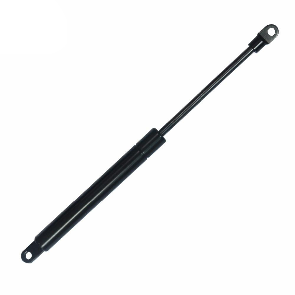
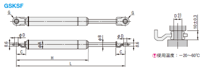
Gas spring, Free attaching direction type, GSKSF type.
Gas Spring Type:Free Mounting Direction
Rod Material:Alloy Tool Steel (SKS Equivalent)
Cylinder Material:STKM11A (Carbon Steel Hollows for Machine Structural Use)
Mounting Orientation:360°
Type:Gas Springs
Drawing/Specifications
| Part Number | Max. Length Lmax | Min. Length Lmin | Stroke | Gas Reaction Force(20°C) | A | B | C | D | G | H | Applicable Mounting Bracket |
Weight(g) | |||||
| Lmax. -10mm Stroke | Lmax.-(S)mm Stroke | ||||||||||||||||
| Type | NO. | N | kgf | N | kgf | (S) | |||||||||||
| GSKSF | 14050-30 | 181 | 131 | 50 | 27 | 2.8 | 35 | 3.6 | 40.0 | 14 | 7 | 15 | 7 | R8 | 110 | GSSB6A | 83 |
| 14050-90 | 85 | 8.7 | 109 | 11.1 | 82 | ||||||||||||
| 14050-150 | 147 | 15.0 | 189 | 19.3 | 82 | ||||||||||||
| 14050-190 | 186 | 19.0 | 239 | 24.4 | 82 | ||||||||||||
| 14050-210 | 206 | 21.0 | 264 | 26.9 | 83 | ||||||||||||
| 14070-90 | 221 | 151 | 70 | 81 | 8.3 | 109 | 11.1 | 60.0 | 130 | 94 | |||||||
| 14070-105 | 104 | 10.6 | 124 | 12.6 | 41.5 | 94 | |||||||||||
| 14070-110 | 280 | 210 | 107 | 10.9 | 144 | 14.7 | 60.0 | 24 | 181 | 119 | |||||||
| 14070-200 | 221 | 151 | 196 | 20.0 | 258 | 26.3 | 15 | 130 | 96 | ||||||||
| 14090-70 | 261 | 171 | 90 | 69 | 7.0 | 95 | 9.7 | 80.0 | 150 | 109 | |||||||
| 14090-80 | 79 | 8.1 | 109 | 11.1 | 108 | ||||||||||||
| 14090-90 | 88 | 9.0 | 122 | 12.4 | 109 | ||||||||||||
| 14090-150 | 147 | 15.0 | 203 | 20.7 | 108 | ||||||||||||
| 14090-200 | 196 | 20.0 | 271 | 27.6 | 107 | ||||||||||||
| 14100-80 | 281 | 181 | 100 | 76 | 7.8 | 106 | 10.8 | 90.0 | 160 | 114 | |||||||
| 14100-110 | 110 | 11.2 | 153 | 15.6 | 112 | ||||||||||||
| 14100-200 | 196 | 20.0 | 273 | 27.8 | 113 | ||||||||||||
| 18090-270 | 261 | 171 | 90 | 263 | 26.8 | 332 | 33.9 | 80.0 | 18 | 8 | 141 | ||||||
| 18100-330 | 281 | 181 | 100 | 324 | 33.0 | 411 | 41.9 | 90.0 | 149 | ||||||||
| 18110-220 | 380 | 270 | 110 | 214 | 21.8 | 272 | 27.7 | 100.0 | 24 | 9 | R10 | 240 | GSSB8A GSSB8B GSSB8C GSSB8D GSSB8E |
200 | |||
| 18150-270 | 475 | 325 | 150 | 267 | 27.2 | 348 | 35.5 | 140.0 | 295 | 252 | |||||||
| 18150-380 | 374 | 38.1 | 487 | 49.7 | 252 | ||||||||||||
| 22080-200 | 279 | 199 | 80 | 196 | 20.0 | 233 | 23.8 | 70.0 | 22 | 10 | 170 | 212 | |||||
| 22080-250 | 246 | 25.1 | 292 | 29.8 | 215 | ||||||||||||
| 22096-400 | 306 | 210 | 96 | 392 | 40.0 | 477 | 48.7 | 86.0 | 181 | 230 | |||||||
| 22100-430 | 375 | 275 | 100 | 427 | 43.6 | 484 | 49.4 | 90.0 | 246 | 267 | |||||||
| 22142-310 | 472 | 330 | 142 | 304 | 31.0 | 348 | 35.5 | 125.0 | 301 | 322 | |||||||
| 22147-150 | 412 | 265 | 147 | 147 | 15.0 | 181 | 18.5 | 130.0 | 236 | 289 | |||||||
| 22147-240 | 240 | 24.5 | 295 | 30.1 | 290 | ||||||||||||
| 22150-350 | 464 | 314 | 150 | 343 | 35.0 | 406 | 41.4 | 140.0 | 285 | 319 | |||||||
| 22200-490 | 600 | 400 | 200 | 481 | 49.1 | 624 | 63.6 | 190.0 | 371 | 424 | |||||||
| 22200-540 | 534 | 54.5 | 693 | 70.7 | 424 | ||||||||||||
| 22235-150 | 580 | 344.5 | 235.5 | 141 | 14.4 | 177 | 18.1 | 206.0 | 315.5 | 386 | |||||||
| 22235-250 | 248 | 25.3 | 311 | 31.7 | 387 | ||||||||||||
| 22235-350 | 343 | 35.0 | 431 | 44.0 | 385 | ||||||||||||
| 22235-510 | 507 | 51.7 | 637 | 65.0 | 389 | ||||||||||||
| 22243-220 | 627 | 384 | 243 | 214 | 21.8 | 273 | 27.8 | 215.0 | 355 | 424 | |||||||
| 22243-480 | 472 | 48.1 | 603 | 61.5 | 424 | ||||||||||||
| 22270-380 | 670 | 400 | 270 | 374 | 38.1 | 464 | 47.3 | 240.0 | 371 | 437 | |||||||
| 22270-560 | 553 | 56.4 | 686 | 70.0 | 441 | ||||||||||||
| 22356-220 | 833 | 477 | 357 | 216 | 22.0 | 280 | 28.6 | 350.0 | 448 | 525 | |||||||
| 22356-350 | 345 | 35.2 | 447 | 45.6 | 527 | ||||||||||||
| 26300-820 | 700 | 400 | 300 | 812 | 82.8 | 1100 | 112.2 | 275.0 | 25 | 12.5 | 20 | 374.5 | 661 | ||||
| 26300-930 | 927 | 94.6 | 1256 | 128.1 | 665 | ||||||||||||
Part numbers
| Part Number | Min. Length Lmin (mm) | Gas Reaction Force (at 20°C) at Max. Length -10mm (N) | Gas Reaction Force (at 20°C) , at Min. Length +10mm (N) | Stroke S (mm) | Rod Dia. d (Ø) | Cylinder Dia. D (Ø) | Max. Length Lmax (mm) | Minimum order quantity |
| GSKSF14050-30 | 131 | 27 | 35 | 50 | 7 | 14 | 181 | 1 Piece(s) |
| GSKSF14050-90 | 131 | 85 | 109 | 50 | 7 | 14 | 181 | 1 Piece(s) |
| GSKSF14050-150 | 131 | - | 189 | 50 | 7 | 14 | 181 | 1 Piece(s) |
| GSKSF14050-190 | 131 | 186 | 239 | 50 | 7 | 14 | 181 | 1 Piece(s) |
| GSKSF14050-210 | 131 | 206 | 264 | 50 | 7 | 14 | 181 | 1 Piece(s) |
| GSKSF14070-90 | 151 | 81 | 109 | - | 7 | 14 | 221 | 1 Piece(s) |
| GSKSF14070-105 | 151 | 104 | 124 | - | 7 | 14 | 221 | 1 Piece(s) |
| GSKSF14070-110 | 210 | 107 | 144 | - | 7 | 14 | 280 | 1 Piece(s) |
| GSKSF14070-200 | 151 | 196 | 258 | - | 7 | 14 | 221 | 1 Piece(s) |
| GSKSF14090-70 | 171 | 69 | 95 | 90 | 7 | 14 | 261 | 1 Piece(s) |
| GSKSF14090-80 | 171 | 79 | 109 | 90 | 7 | 14 | 261 | 1 Piece(s) |
| GSKSF14090-90 | 171 | 88 | 122 | 90 | 7 | 14 | 261 | 1 Piece(s) |
| GSKSF14090-150 | 171 | - | 203 | 90 | 7 | 14 | 261 | 1 Piece(s) |
| GSKSF14090-200 | 171 | 196 | 271 | 90 | 7 | 14 | 261 | 1 Piece(s) |
| GSKSF14100-80 | 181 | 76 | 106 | - | 7 | 14 | 281 | 1 Piece(s) |
| GSKSF14100-110 | 181 | 110 | 153 | - | 7 | 14 | 281 | 1 Piece(s) |
| GSKSF14100-200 | 181 | 196 | 273 | - | 7 | 14 | 281 | 1 Piece(s) |
| GSKSF18090-270 | 171 | 263 | 332 | 90 | - | - | 261 | 1 Piece(s) |
| GSKSF18100-330 | 181 | 324 | 411 | - | - | - | 281 | 1 Piece(s) |
| GSKSF18110-220 | 270 | 214 | 272 | 110 | - | - | 380 | 1 Piece(s) |
| GSKSF18150-270 | 325 | 267 | 348 | 150 | - | - | 475 | 1 Piece(s) |
| GSKSF18150-380 | 325 | 374 | 487 | 150 | - | - | 475 | 1 Piece(s) |
| GSKSF22080-200 | 199 | 196 | 233 | - | - | - | 279 | 1 Piece(s) |
| GSKSF22080-250 | 199 | 246 | 292 | - | - | - | 279 | 1 Piece(s) |
| GSKSF22096-400 | 210 | 392 | 477 | 96 | - | - | 306 | 1 Piece(s) |
| GSKSF22100-430 | 275 | 427 | 484 | - | - | - | 375 | 1 Piece(s) |
| GSKSF22142-310 | 330 | 304 | 348 | 142 | - | - | 472 | 1 Piece(s) |
| GSKSF22147-150 | - | - | 181 | 147 | - | - | 412 | 1 Piece(s) |
| GSKSF22147-240 | - | 240 | 295 | 147 | - | - | 412 | 1 Piece(s) |
| GSKSF22150-350 | 314 | 343 | 406 | 150 | - | - | 464 | 1 Piece(s) |
| GSKSF22200-490 | 400 | 481 | 624 | 200 | - | - | - | 1 Piece(s) |
| GSKSF22200-540 | 400 | 534 | 693 | 200 | - | - | - | 1 Piece(s) |
| GSKSF22235-150 | 344.5 | 141 | 177 | 235.5 | - | - | 580 | 1 Piece(s) |
| GSKSF22235-250 | 344.5 | 248 | 311 | 235.5 | - | - | 580 | 1 Piece(s) |
| GSKSF22235-350 | 344.5 | 343 | 431 | 235.5 | - | - | 580 | 1 Piece(s) |
| GSKSF22235-510 | 344.5 | 507 | 636 | 235.5 | - | - | 580 | 1 Piece(s) |
| GSKSF22243-220 | 384 | 214 | 273 | 243 | - | - | 627 | 1 Piece(s) |
| GSKSF22243-480 | 384 | 472 | 603 | 243 | - | - | 627 | 1 Piece(s) |
| GSKSF22270-380 | 400 | 374 | 464 | - | - | - | 670 | 1 Piece(s) |
| GSKSF22270-560 | 400 | 553 | 686 | - | - | - | 670 | 1 Piece(s) |
| GSKSF22356-220 | 476.5 | 216 | 280 | 356.5 | - | - | 833 | 1 Piece(s) |
| GSKSF22356-350 | 476.5 | 345 | 447 | 356.5 | - | - | 833 | 1 Piece(s) |
| GSKSF26300-820 | 400 | 812 | 1100 | 300 | - | 25.4 | 700 | 1 Piece(s) |
| GSKSF26300-930 | 400 | 927 | 1256 | 300 | - | 25.4 | 700 | 1 Piece(s) |